Related Wiring Diagrams:
- How to wire a Single Pole Single Throw (SPST) switch? IEC and NEC
- How to wire a single pole double throw (SPDT) switch? IEC and NEC
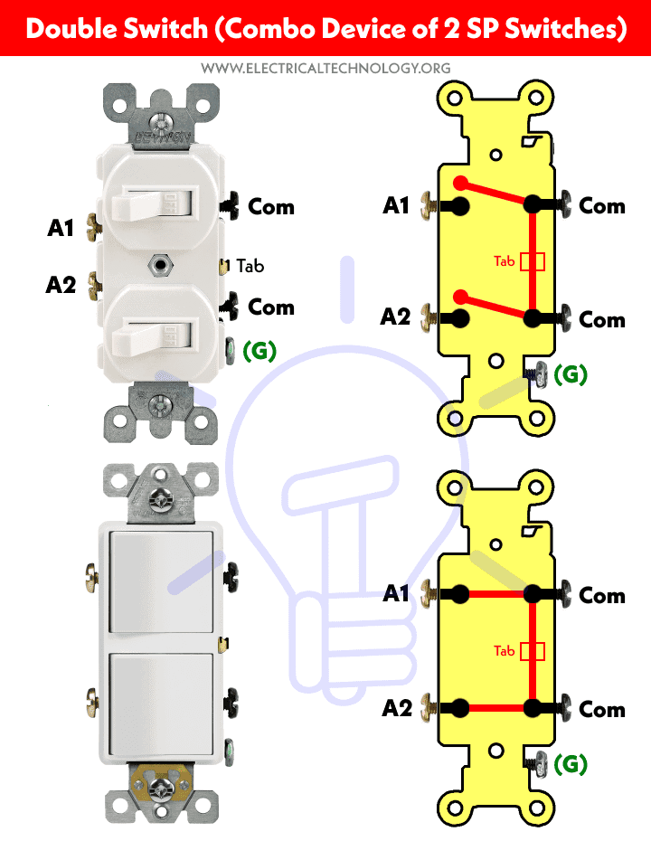
Construction of Combination Device (Double Switch or 2 Gang, 1 Way)
The following figures represent the basic construction of (NEC ) and a two-gang unidirectional (IEC) switch.
Click image to enlarge

The following diagram shows the operating operations of a double breaker (combination of two breakers in a single unit).
Click image to enlarge
The following figures show the di Different views of the combo device of double breaker.
Click on the image to enlarge it

Let’s see how to connect them one by one for different load circuits according to NEC and IEC.
Wiring of double switches for 120V/240V Circuits – NEC
How to wire a double switch to a ceiling fan with one bulb in one unit?
The diagram below The wiring diagram shows how to control both the light and the fan using a dual combo switch.It clearly shows that the Hot (Line) wire is connected to common screws that are attached to each other via a breakaway tab.There are four wires connected to the ceiling fan terminal box with a light bulb.
Click image to enlarge

The red wire is connected to the ceiling fan and the black wire is connected to the light bulb from the Dual Switch Load Terminals. Finally, the Ground and Neutral wire connects to the terminals (common to both fixtures) on the ceiling fan box. In this way, the upper switch controls the fan and the lower switch controls the light bulb for ON and OFF operations.
Note that you can use the combination of the fan and dimmer switch of the light control. the light for the same purpose since it has the same wiring connections.
Related Posts:
- How To Wire Switches In Series?
- How to wire switches in parallel?
Wiring Combined device with a single pole duplex Swap to a ceiling fan and light bulb?
The diagram below shows control of a regular fan and separate light bulb using a double (combination) switch. It has the same wiring connection as the previous one. The incoming hot wire is connected to the common screw of the double switch. The load terminals connected to the ceiling fan and light bulb. Also, both the neutral and ground wires are connected to the fan and light.
Click the image to enlarge it

In this case, the top switch (red wire from switch to fan) controls the ceiling fan and switch The bottom switch (black wire from switch to fan) controls the ceiling fan and the bottom switch (black wire from switch to fan). light) controls the bulb.
Wiring a ceiling fan and light using a dual combination dimmer switch
This is the recommended way of wiring a fan and light using a dual dimmer switch combination to control fan speed and light density.
As shown, the (hot) line is connected to the common screw on the switch of attenuation. The dual dimmer switch load terminals are connected to the fan and light bulb. Finally, both the neutral and ground wires are connected to both charging points.
Click on the image to enlarge it

As shown, the upper switch is used to control fan speed, while the lower switch is used to control light density, as well as operations ON and OFF.
Related posts:
- How to connect lamps in series?
- How to connect lamps in parallel?
Wiring of 1-way 2-gang light switches for 230V circuits – IEC
Control of a fan and a light bulb in a single unit using a two-gang 1-way switch
The following wiring diagram shows how to control both the ceiling fan and light bulb using a two-gang 1-way switch. As shown, the phase (line) wire is connected to both common screws. There are four wires connected to the ceiling fan terminal box with a light bulb.
Click image to enlarge

Brown wire as phase of switch L1 terminal is connected to ceiling fan and black wire as phase of switch L2 terminal is connected to light . bulb. Finally, the neutral and ground wire connect to the common terminals in the ceiling fan box. This way, the first switch controls the fan and the second switch controls the light bulb for ON and OFF operations.
Remember that you can use the combination of the fan and the dimmer switch of the light control. light for ON and OFF operations. it serves the same purpose as it has the same wiring connections.
Related Posts:
- How to Wire a Single Pole Double Throw (SPDT) Switch ? IEC and NEC
- How to wire a Double Pole Double Throw (DPDT) switch? IEC and NEC
- How to wire a 4-way switch (NEC) and an intermediate switch as a 3-way (IEC)?
Wiring a Ceiling Fan and Light Bulb Using a 2-Way and 1-Way Switch
The following wiring diagram shows the control of a typical fan and a separate bulb using a two -gang, one-way switch. It has the same wiring connection as shown above. The incoming phase wire is connected to the common terminal of the 2-gang switch. The load terminals (L1 and L2) connected to the ceiling fan and light bulb respectively. Also, both the neutral and ground wires are connected to both the fan and the bulb.
Click the image to enlarge it

In this case, the right-hand switch (brown wire from switch terminal L1 to fan) controls ON and OFF operations. Ceiling fan OFF and left side switch ( The black wire from the L2 terminal of the switch to the light controls the ON/OFF operations of the bulb.
Related Posts:
- How to control a lamp by a one-way or one-way switch?
- How to control each lamp by an independent switch in a pairwise lighting circuit allele?
- Brass screws should be connected to the Hot wire (line, hot, or phase) using IEC and NEC wire color codes. In the case of SPDT and 4-way (intermediate switches), black colored screws are used for the hot or common terminals. In short, the color of the common terminal is different from other terminals.
- The silver screws should be connected to the neutral wire (in case of switched outlet)
- The green screw must be connected to the ground/ground wire (green/yellow or bare wire)
- If there are no color-coded screws on the outlets, consult the owner’s manual or contact a certified electrician.
- Neutral is not required in wiring 240V (US) outlets. Also, neutral is never connected to switches.
- Use the voltage and rating of proper switch amps with proper wire size and proper MCB size according to the rated load.
Cautions:
- Turn off the main circuit breaker to ensure the power supply is OFF before wiring an existing cable. or a new outlet or switch with an electrical/junction box.
- Contact the licensed and licensed electrician for switch installation if you are unsure about the wiring diagrams.
- The author r shall not be liable for any loss, injury, or damage arising from the display or use of this information or if you test any circuitry in an incorrect format. So please! Be careful because it’s all about electricity and electricity is too dangerous.
.